Systems
Source: en.tmotor.com[ Cover Source ]
Systems PUBLISHED
How FPV Systems Work Together: System Integration & Electrical Architecture
A comprehensive systems engineering study on the FPV aircraft as an integrated electrical and signal processing system.
FPVLOVERS EDITORIALJune 2, 20263 field notesguide
1. The FPV Aircraft as an Integrated System
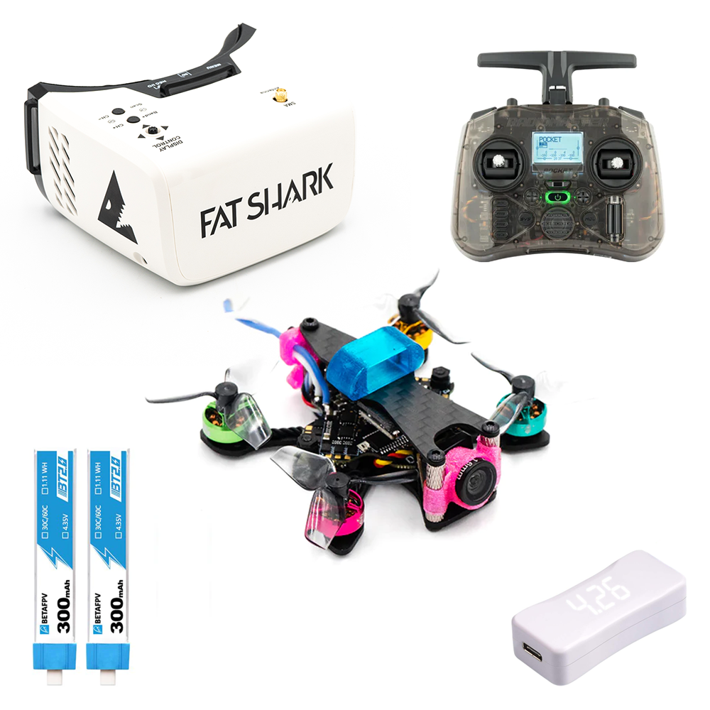
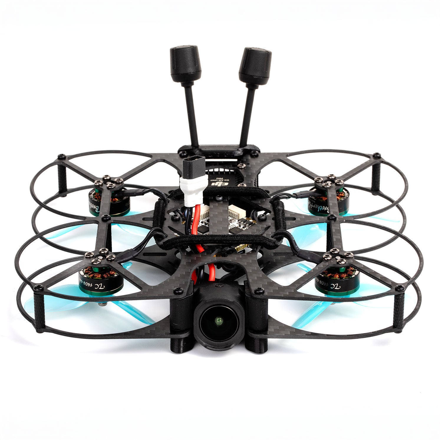
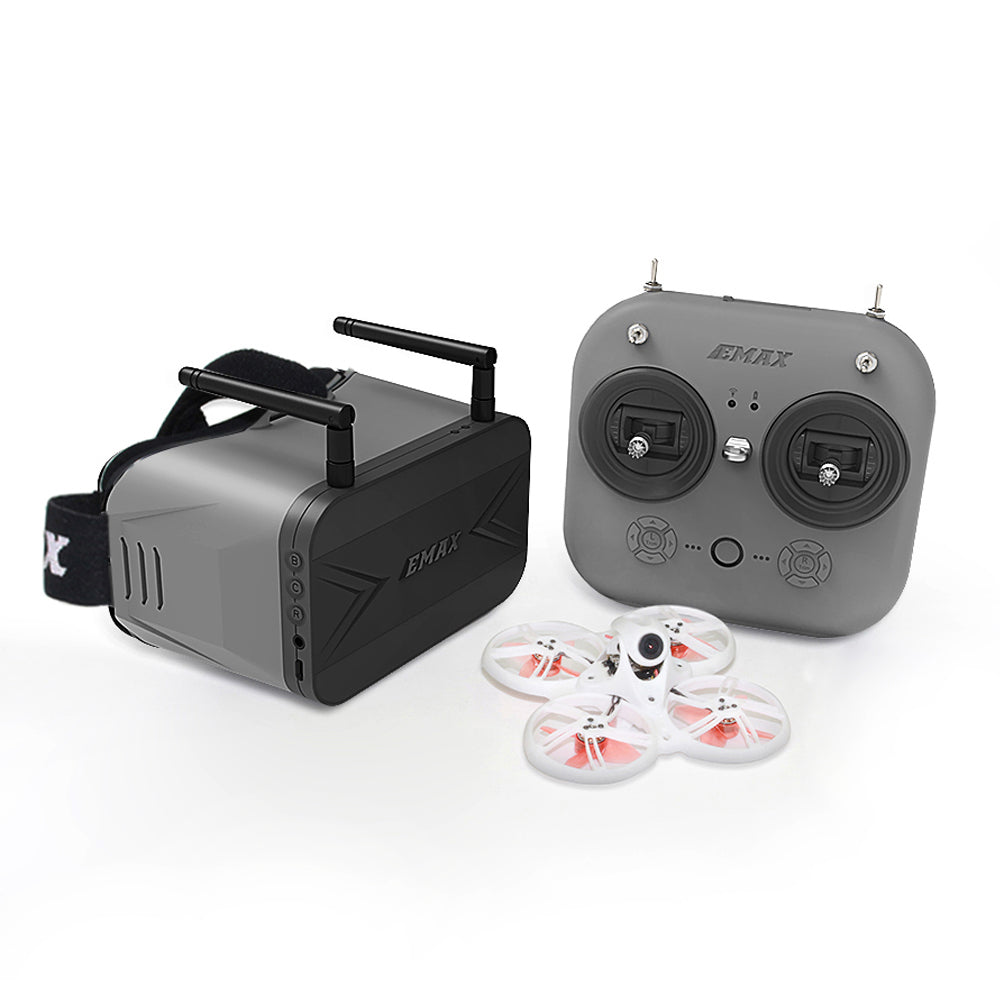
An FPV multirotor is an interconnected system of electrical, radio, and mechanical components. Every system depends on the others; a flaw in one component cascades through the entire aircraft.
Source: en.tmotor.com[ View Source ]
2. Core Subsystems
2.1 The Electrical Bus
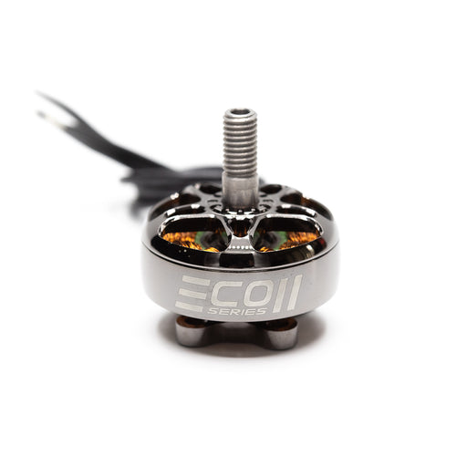
The battery delivers raw power (up to 25V) to the ESC. The ESC regulates motor speeds and supplies clean $5\text{V}$ and $9\text{V}$ power to the Flight Controller (FC), radio receiver (RX), and video transmitter (VTX).
2.2 Signal Pathways
- Pilot Inputs are transmitted via RF waves ($2.4\text{ GHz}$) to the RX.
- RX forwards digital packets (using CRSF protocol) to the FC.
- FC reads gyro sensors, runs PID calculations, and sends motor commands to the ESC via DShot.
[Multirotor Signal Architecture]
Pilot Sticks ---> Tx (Radio) ---> Rx (Receiver) ---> FC (Flight Controller)
                                                        |
Gyro Telemetry <--- Motors <--- ESC (Motor Speed) <-----+
3. Common System Cascading Failures
- Electrical Ground Loops: Bad grounding routes electrical noise from the motors directly into the analog video line, causing heavy diagonal line static in the goggles.
- Voltage Sag Crashes: High-current motor loads can sag battery voltage below the FC regulator's minimum input, triggering an immediate mid-air flight controller reboot.
RELATED GUIDES
Copyright-safe media generated locally by FPVLovers